wattstopper wiring diagram
7m Coverage shown is for half-step walking motion maximum of 900 sq ft. Wiring diagram that is appropriate to the PW model and.

Watt Stopper Power Pack Wiring Diagram Sherriescraos
A wiring diagram usually gives information practically the relative slant and bargain of devices.

. They are the foundation of a Wattstopper Digital Lighting Management DLM system and allow integration of. Coverage Wiring Coverage Pattern Wiring Diagrams Multi-way wiring Note. When using more sensors than this multiple power packs are required.
Connect the low voltage. Cap off the 3-way wire with a wire nut in a single pole installation. It describes how the electrical circuits are interrelated and may show exactly where distinct elements and fixtures are situated in relation to each other.
Installation Wiring Installation Diagram Wiring with Occupancy Sensor Manual-on Bi-level Switching Installation Diagram Low-voltage Momentary Switch Options By using two low-voltage switches a ceiling sensor and two BZ-150s one set to Auto ON and one set to Manual ON bi-level switching with manual-on operation can be achieved. RED wire 24VDC from power pack Commo to the 24V terminal on the sensor. WIRING DIRECTIONS Each Wattstopper BZ series power pack can supply power for 7 DT-305 sensors.
DW DW The DW has one relay and one ONOFF button. It shows the components of the circuit as simplified shapes and the knack and signal connections between the devices. When used in a multi-way application all devices in that space must be wired using the same method of either with neutral or without neutral.
Legrand watt stopper dt 305 quick start manual pdf manualslib wattstopper pw 311 installation instructions power pack 120 277v 50 60hz 24vdc 225ma w auto on packs occupancy and vacancy sensors lighting controls systems lmrc 100 series digital switching room. Wattstopper Lmrc-211 Wiring Diagram. All units should be on the same phase.
BLACK wire Return. The Emergency wiring leads on the ELCU in series with the emergency lighting load as shown in the wiring diagram. Wattstoppers industry-leading energy efficient lighting controls technology and services offering is designed to meet code.
Legrands Wattstopper product line of Lighting Control Systems and Services is the most comprehensive line of simple scalable and flexible energy-efficient lighting and plug load controls for commercial applications. The 2 ground wires green and green yellow must be fastened to ground for the sensor to work properly. On the part of WattStopper for consequential damages arising out of or in.
When using more sensors than this multiple power packs are required. 16A 2 4 LMPB-100 Provides local network power for LMFC controllers plus any other DLM devices. When using more sensors than this multiple power packs are required.
In Normal Power Emergency Power Line Out In Neut Emergency Lighting Emergency Line Emergency Neutral Sensing Line Switching Line Remote Out 24VDC ELCU-100 Normal Line Normal Neutral. Wiring Mounting Wiring Diagram Ceiling Mounting Controls Settings Product Controls DIP Switch Settings Coverage Placement Coverage Patterns Catalog Voltage Load Rating Coverage DT-355 0-800W BallastTungstenLED DT-355-U 120 VAC 5060 Hz 277 VAC 5060 Hz 347 VAC 5060 Hz 0-1200W BallastLED 0-1500W BallastLED up to 1000 ft 2 929 m. Connect wires to the PW flying leads as shown in the wiring diagram that is appropriate to the PW model and electrical supply.
Wiring Diagram Coverage Pattern Terminal style wiring for easy installation Built-in light level sensor ASIC technology Zero Crossing Circuitry increases longevity Attractive low-profile appearance Adjustable sensitivity 15 46m 35 10. RED wire 24VDC from power pack to. Cat 5e wiring lengths shall be field cat 5e wiring lengths shall be field assembled by the contractor對.
Wattstopper Occupancy Sensor Wiring Diagram. Attach the sensor to the wall box by inserting screws into the. Connect the low voltage.
Each WattStopper BZ series power pack can supply power for 5 DT-300 sensors. Connect the WattStopper warranties its products to be free of defects in materials. WattStopper radiant.
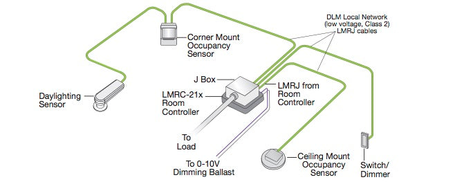
LMRC-210 Series Digital Room Controllers include one two or three relays to switch a total of 15 or 20 amps a highefficiency switching power supply and one 0-10 volt output per relay for control of dimmable loads including electronic ballasts Advance Mark 7 or equivalent. 16A 1 4 LMRC-222 2-Relay Room Controller Forward Phase Dimming with Calculated Plus Metering provides 24VDC. The ELCU Emergency Lighting Control Unit allows lighting control devices for circuit to the Emergency Neutral lead as shown in the wiring diagram.
The ground wire green must be fastened to ground for the sensor to work properly. Connect the low voltage. Connect wires to the DW flying leads as shown in the wiring diagram below.
Wattstopper Passive Infrared Multi-Way Switch Occupancy Sensor. Wattstopper dlm wiring diagram keyword after analyzing the system lists the list of keywords related and the list of websites with related content in addition you can see which keywords most interested customers on the this website. Each Wattstopper BZ series power pack can supply power for 3 DT-205 sensors.
WIRING DIRECTIONS Each WattStopper BZ series power pack can supply power for 5 UT-300 sensors. WattStoppers ELCU Emergency Lighting Control Unit is a self-contained. 250mA 120277VAC Incandescent MLV ELV LED FP compatible.
Lmrc-213 triple relay 0-10v dimming wiring diagram. For typical desktop activity. When using more sensors than this multiple power packs are required.
Refer to the wiring diagram on the next page for the following procedures. Wattstopper Dcc2 Wiring Diagram wiring diagram is a simplified enjoyable pictorial representation of an electrical circuit. Connect the LOW VOLTAGE.
Refer to the wiring diagram on the next page for the following procedures. Use green jacketed cat 5e cable to avoid use green jacketed cat 5e cable to avoid confusion with voice ata av and security. Wattstopper Wiring Diagrams A wiring diagram is an straightforward visual representation of a circuits physical structure and electrical connections.
12 The DW dual technology wall switch sensor combines. ELCU Wiring Diagrams Jumper Wire or Normally Closed Input from Test Switch Fire Alarm Input Security Input Other Remote In Switch In Line Neut. Install dimmer in wall box with word TOP on the strap right side up using mounting.
Connect the ELCU to the control device for the area controlled. 2-wire or 3-wire ballast. Connect dimmer as shown in the wiring diagram using 12 or 14 AWG stranded or solid copper conductors Figure 1.
Connect the neutral for the emergency circuit to the Emergency Neutral lead as shown in the wiring diagram. 2-wire or 3-wire ballast. WattStopper DW series wall switches fit behind industry standard decorator-style.
For best performance Wattstopper recommends. Cu Wire OnlyAttach the sensor to the wall box by inserting screws into. By Admin October 21 2017.
WIRING DIAGRAMS FOR DIMMERS 6. RED wire 24VDC from power pack to the 24V terminal on the sensor. Wattstopper The DW has one relay and one ONOFF.
Installation in any 2-wire or 3-wire application. RED wire 24VDC from power pack to the 24V terminal on the sensor. LMRC Digital OnOff Volt Dimming Room Controller with 1 relay and 1.
Wattstopper Wiring Diagrams - Temperature Control Systems is a full line The MPP ceiling sensor power pack is the foundation for any low voltage lightingThe BZ power pack switches connected loads On and Off in response to Wattstopper low voltage occupancy sensors. Refer to the wiring diagram on the next page for the following procedures. Feb 24 Digital Lighting Managements modular design makes installation a snap taking just half the time to.
Wattstopper Elcu-200 Wiring Diagram. Refer to the wiring diagram on the next page for the following procedures.
Bcxa Org
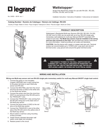
Legrand Rh 253 Single Pole Momentary Switch For Use Installation Instruction Manualzz
Media Distributordatasolutions Com
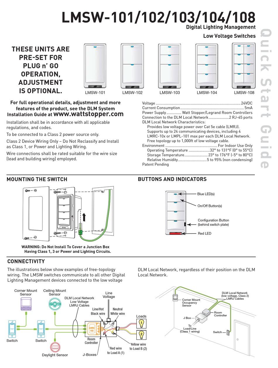
Wattstopper Lmsw 102 Quick Start Manual Pdf Download Manualslib

Ultrasonic Ceiling Occupancy Sensor 24vdc 600 Sq Ft Wall Switch Occupancy And Vacancy Sensors Occupancy And Vacancy Sensors Lighting Controls And Systems
Choosing Wattstopper Dlm Product Literite Controls
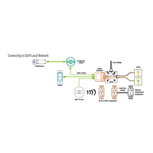
Wattstopper Wrc 15 20 Amp Wireless Receptacle Control Literite Controls
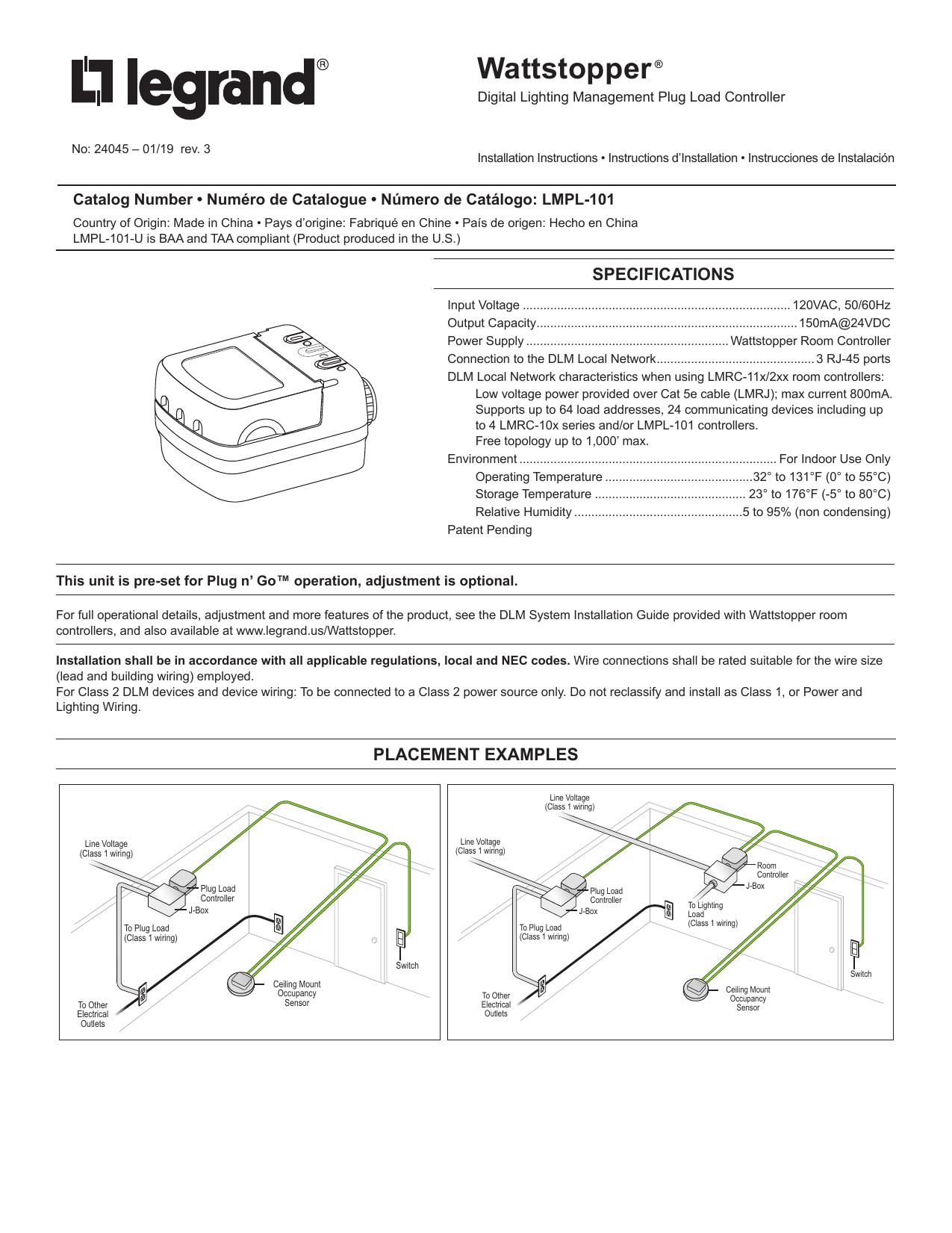
Legrand Lmpl 101 Dlm Plug Load Controller Quick Start Installation Instruction Manualzz
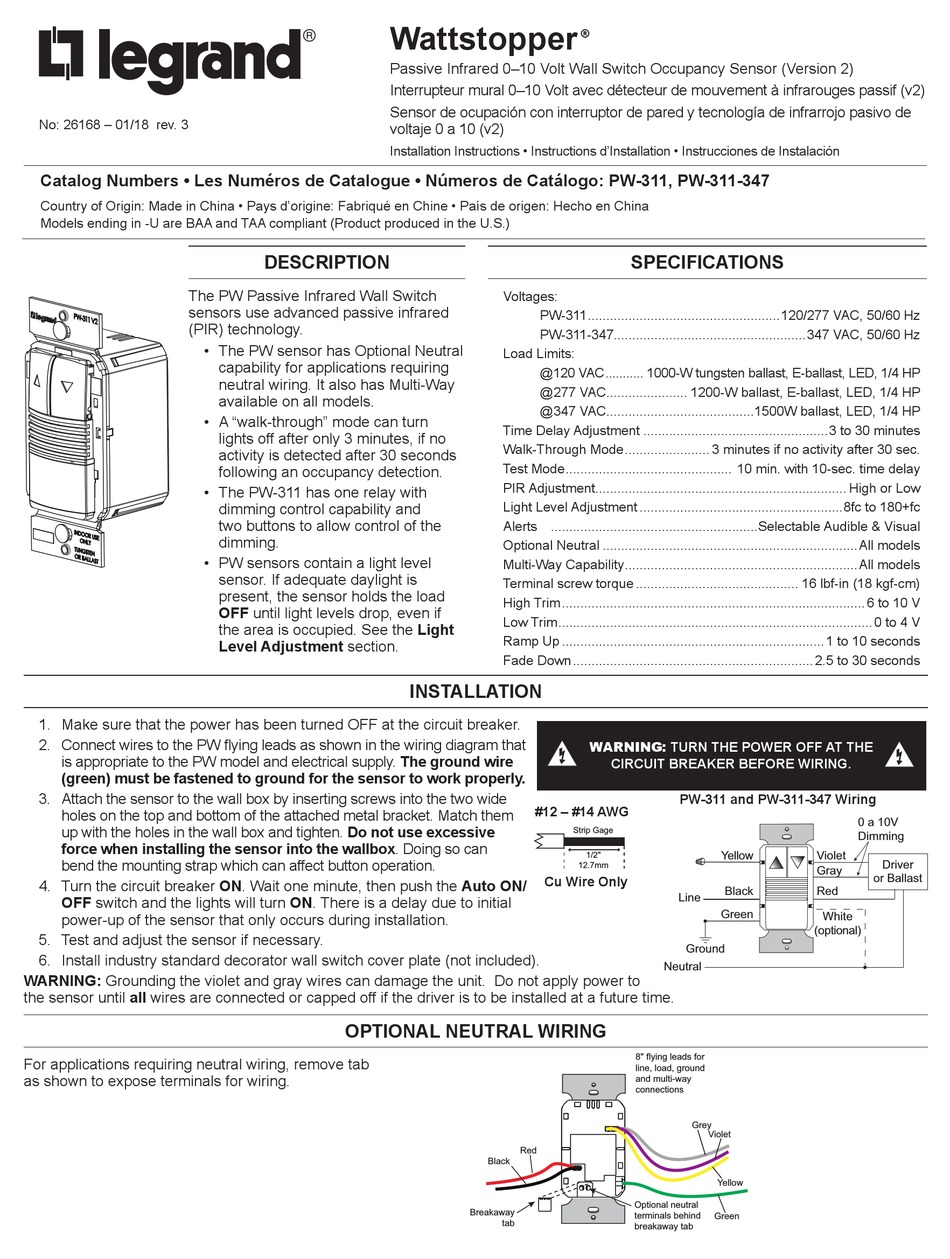
Legrand Wattstopper Pw 311 Installation Instructions Manual Pdf Download Manualslib

Legrand Lmrc 213 Dlm Triple Relay W 0 10v Dimming Room Controller Quick Start Installation Guide Manualzz
1 Wattstopper Elcu 200 Emergency Lighting Cnotrol Unit Power Pack White Amazon Ca Electronics
Ultrasonic Ceiling Occupancy Sensor 24vdc 600 Sq Ft Wall Switch Occupancy And Vacancy Sensors Occupancy And Vacancy Sensors Lighting Controls And Systems
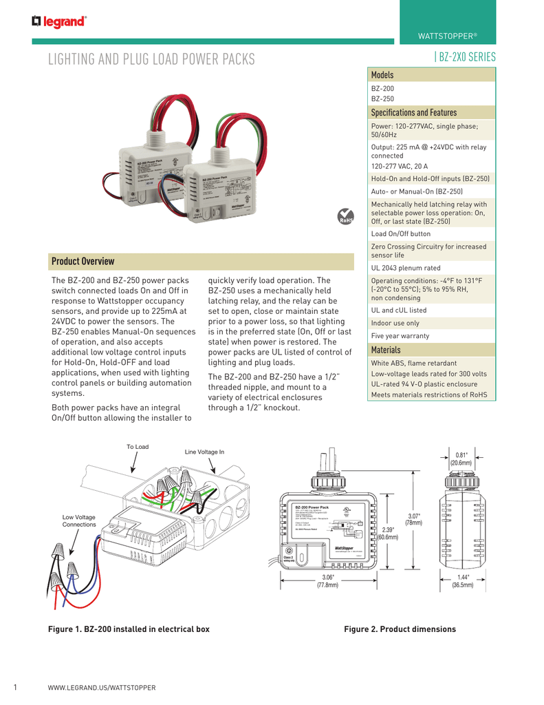
Lighting And Plug Load Power Packs Manualzz
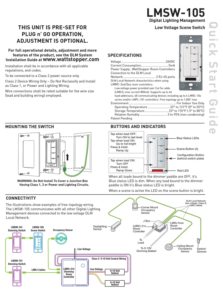
Wattstopper Lmsw 105 Quick Start Manual Pdf Download Manualslib
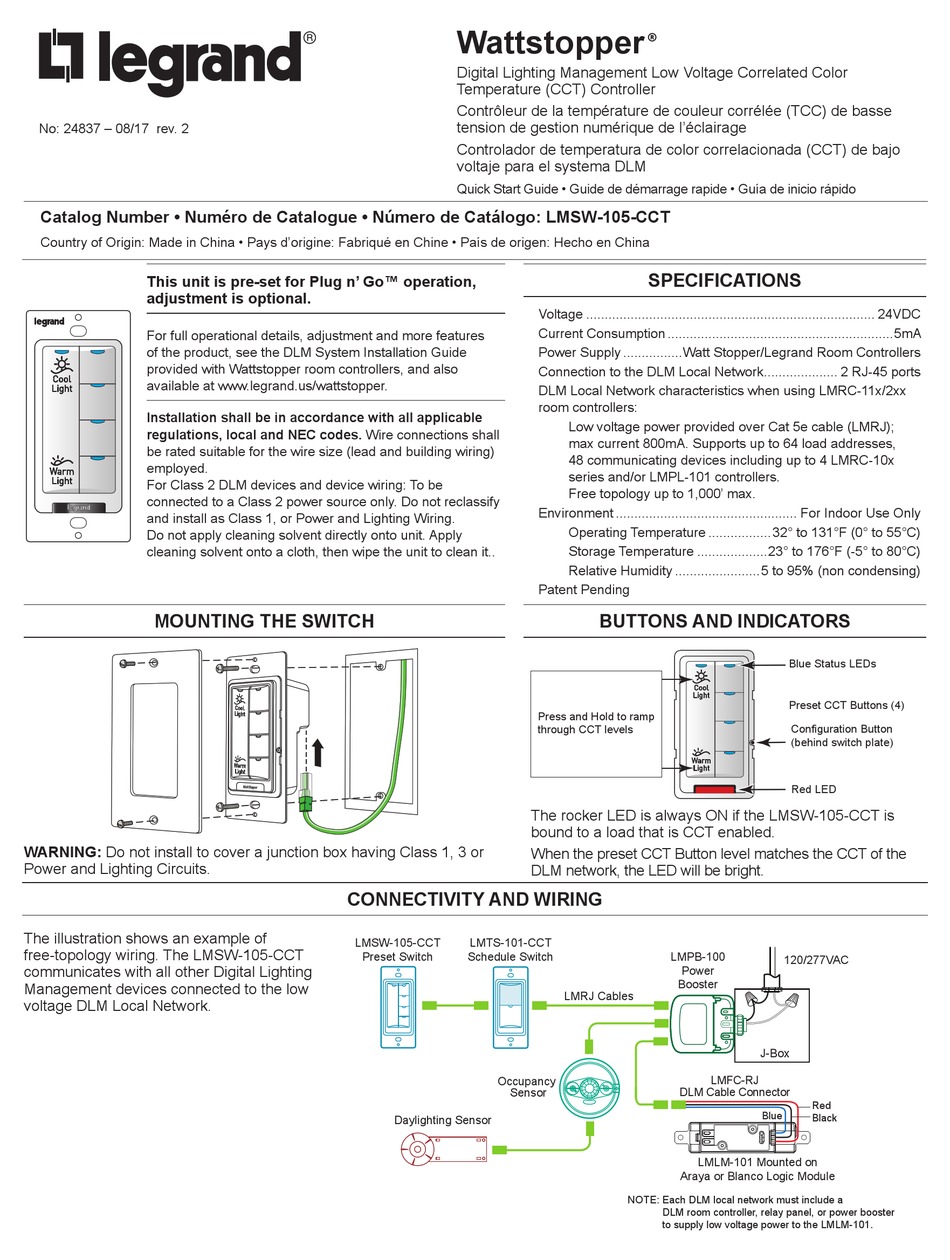
Wattstopper Lmsw 105 Cct Installation Manual Pdf Download Manualslib
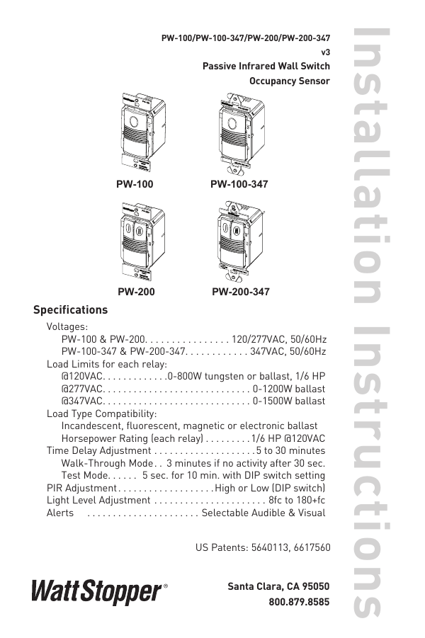
Wattstopper Legrand Pw100w Installation

Legrand Watt Stopper Dt 305 Quick Start Manual Pdf Download Manualslib
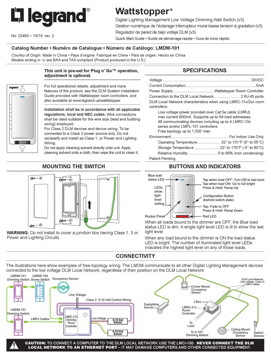
Legrand Wattstopper Lmdm 101 Quick Start Manual Pdf Download Manualslib
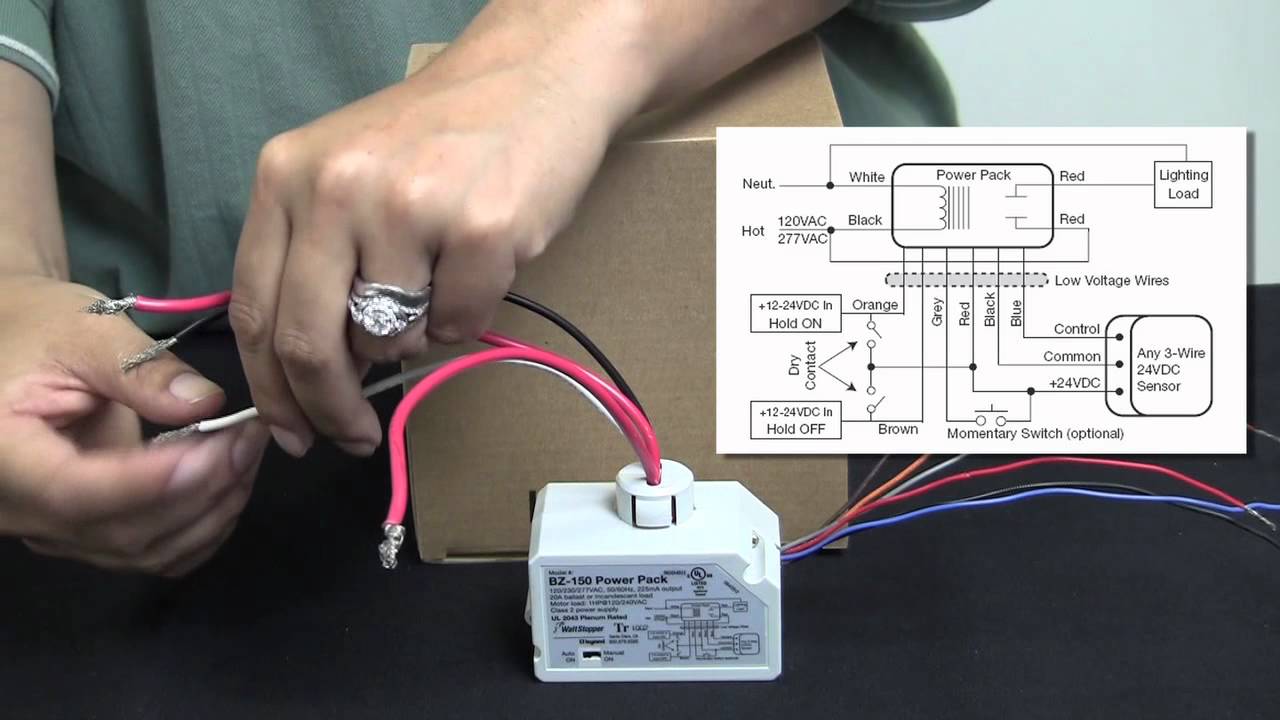
Wattstopper How To Wiring A Bz 150 Universal Voltage Power Pack Youtube